Introduction
Setup Sensor Configuration
Requires administration privileges.
Sensor Configuration is the first step of initializing the NetMeter.
Initially, the configuration screen looks like:
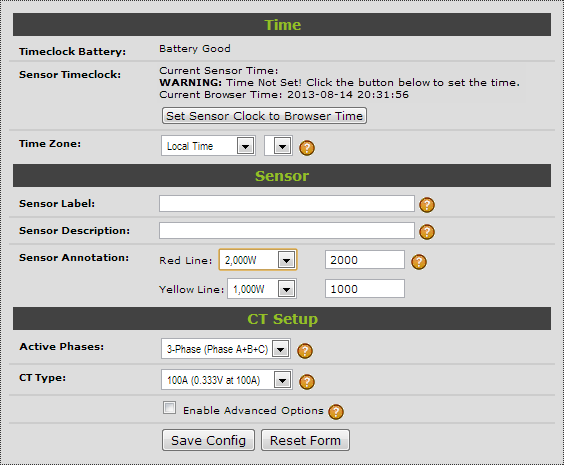
Basic Setup
There is a minimum set of 4 items to be configured. Everything else is optional:
- Set the time clock
- Enter a Sensor Label
- Enter a Sensor Description
- Configure the CT type
Make sure you press Save Config to store the configuration changes.
Timeclock Battery
If "Battery Good" is not displayed, then the real-time clock battery should be replaced. See the user manual for battery replacement instructions.
Sensor Timeclock
Click Set Sensor Clock to Browser Time to set the NetMeter timeclock. This relies on the accuracy of the timeclock of the computer you are using to do this set up.
Make sure that your PC is set up for timeclock synchronization to an accurate reference source (further information here).
Time Zone
Leave this set to Local Time.
Sensor Label
This should be a brief mnemonic to identify the NetMeter. Must be an alphanumeric text string up to 46 characters. Do not use special characters.
Examples:
- MCC-1
- Boiler
- Chiller-1
- Main-Circuit
Sensor Description
This should be a more descriptive way of identifying the NetMeter. Must be a text string up to 46 characters. Do not use special characters.
Examples:
- Lighting for West Wing
- 20 Ton Chiller
- Total Building Consumption for Toronto Office
Sensor Annotation
The red line/yellow line values are used to color code some of the graphical plots. The color of the plot will transition from green (starting at zero) towards yellow and then to red. Consequently, it is important that the yellow value be less than the red value.
The example below shows a red line set to 30,000 Watts and a yellow line set to 15,000 Watts.
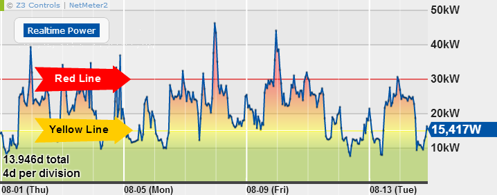
Set the red yellow values to zero to disable color coding.
Active Phases
This is used to determine how many phases will be added into the cumulative total energy. When upper phases are disabled, they continue to operate as normal with the exception that the combined energy/power will only include active phases.
CT Type
This should be set to match whatever type of CT you are using. Select from one of the presets or choose "Custom" if you're CT is not available in the list.
![]()
For custom CTs, enter the Volts and Amps values into the available box so that they correspond to the CTs that are being used.
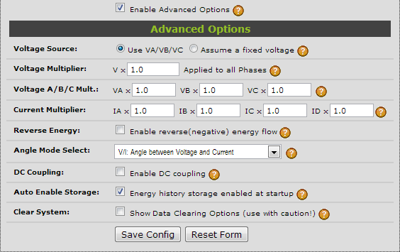
Advanced Setup Options
Click the "Enable Advanced Options" for additional setup parameters. This is intended for advanced users and for greater application flexibility:
- DC applications
- Reverse energy
- Scale factor for the use of potential transformers (PTs)
- Data clearing options
Voltage Source
Select "Use VA/VB/VC" for normal operation where phase voltages are connected.
When the voltage inputs are not connected, select "fixed voltage" mode and enter an assumed voltage:
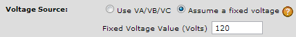
Be sure and enter the Wye (Y) equivalent voltage and not the Delta (Δ) voltage. For example, a 600V circuit would be entered as 347 (600 divided by the square root of 3). These are some of the common Wye/Delta voltages combinations:
| Delta Voltage | Wye Voltage |
|---|---|
| 600V | 347V |
| 575V | 332V |
| 480V | 277V |
| 240V | 139V |
| 208V | 120V |
For more information about Wye/Delta see the FAQ: Why is the NetMeter voltage reading much lower than I expect?
The fixed voltage mode does not allow a true power calculation including power factor. The resulting data will suffer in accuracy.
When using the fixed voltage mode it may be desirable to scale back the fixed voltage value in order to help compensate for non-ideal power factor. For example, if you believe your power factor to be about 90%, then use A 10% lower Fixed Voltage Value to more closely estimate your true power.
Voltage Multiplier and Voltage A/B/C Mult.
There is a global voltage multiplier ("Voltage Multiplier") that affects all of the voltage inputs. It is intended to be used when potential transformers are in use. For example, if a 10:1 PT is being used, then the Vx value should be set to 10.
"Voltage A/B/C Mult." provides a per phase multiplier that can be used for fine tuning differences between the phases. For example, a multiplier of 1.05 will increase the effective voltage reading by 5%. A multiplier of 0.95 will reduce the voltage reading by 5%. The A/B/C multipliers must be between between 0 and 2.
Current Multiplier
A current multiplier can be applied individually to each of the CT inputs. Current multipliers must be between 0 and 2.
The multiplier values can be used to manually calibrate the CTs. For example, a multiplier of 1.05 will increase the effective current reading by 5%. A multiplier of 0.95 will reduce the current reading by 5%.
Reverse Energy
When "Enable reverse(negative) energy flow" is disabled (default) then CT polarity is effectively ignored for the purposes of power/energy calculation.
Reverse energy need only be enabled when energy flow can be in either direction (both consumption and generation). This may be the case for applications where there is both generation ( solar, wind, etc.) and energy consumption on the same circuit. This feature should also be enabled for monitoring loads that have electronic braking or some type of energy recovery such as elevators that recover energy during braking.
Angle Mode Select
Selects what inputs are used to calculate phase angle for realtime display and for the advanced data logger. The options are:
- V/I: Angle between Voltage and Current (Default):
- Phase A is the angle between VA and IA, Phase B is the angle between VB and IB, Phase C is the angle between VC and IC,
- V/V: Angle between the Voltages:
- Phase A is the angle between VA and VB, Phase B is the angle between VB and VC, Phase C is the angle between VC and VA.
- I/I: Angle between the Currents:
- Phase A is the angle between IA and IB, Phase B is the angle between IB and IC, Phase C is the angle between IC and IA.
DC Coupling
"Enable DC coupling" is disabled by default. It should only be enabled for DC applications such as solar (DC side of inverter).
Auto Enable Storage
"Energy history storage enabled at startup" controls the default data logger. When enabled (default), the NetMeter will automaticaly store energy use data whenever it is turned on or reset. It should be enabled for normal operation.
The advanced data logger is enabled through the Datalog Configuration screen.
Clear System
Click "Show Data Clearing Options" to reveal 2 buttons
- Clear Data: clears all of the stored data and resets the time clock. The NetMeter should be power cycled after this in order to reset it.
- Clear Data and Configuration: this operation effectively restores the NetMeter to its default factory condition.
Testing/Troubleshooting Your Setup
In order to ensure that the sensor is set up properly, navigate to the Details page and check the voltage/current readings to make sure they look reasonable.
Remember that the voltage reading is the Wye voltage, not the Delta voltage. If the voltage reading looks lower than you expect, check the following FAQ: Why is the NetMeter voltage reading much lower than I expect?
A common problem for NetMeter installation is proper CT phasing and polarity:
- CT Phase Mismatch:
- This happens when the voltage is not properly paired with the corresponding CT. Ensure that voltage phase A matches CT phase A and so on.
- CT Polarity Mismatch: this happens when the CT is on backwards or the leads on the CT are on backwards where they connect to the NetMeter.
The Details page is the best place to troubleshoot CT phasing/polarity issues. Further explanation is available here: Troubleshooting CT Phase/Polarity Errors.