Introduction
This page describes the NetMeter-OMNI-8C terminal connections.
Safety Notice
Safety procedures and additional connection information is described in the Installation Manual:
| User Manuals | ||||
|---|---|---|---|---|
| Title | Type | Size | Date | Note |
| NetMeter-OMNI-8C Installation Manual |  |
3.4MB | 2014-02-19 | |
Connection Diagram

The connectors are:
- Supply Voltage
- A low voltage DC power supply (18-28V, 24 volt nominal) provides the power required to operate the NetMeter-OMNI
- The supply voltage terminals will work with either polarity
- ZCAN Connector
- Provides expansion capabilities for the NetMeter-OMNI to communicate with Z3 accessories
- Ethernet Connector
- This is a standard 10/100 Mb RJ45 Ethernet port that should be connected to an Ethernet switch/router using standard (CAT5/CAT5e/CAT6) network cable.
- Switch Contact Backup Voltage Terminals (VB)
- For use with dry contact switches or KYZ contacts from pulse devices that may pulse even during power outages. The VB terminals output a current-limited small voltage that exists even during power failure.
- Input 0 – Input 7 Terminals
- These are the input terminals for each of the 8 sensor channels. Each input can be individually configured as voltage or current mode.
- Ground Terminals
- Common ground across all inputs.
Voltage Mode Connection Diagram
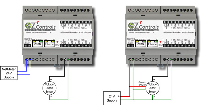 Connection of Voltage Output Sensors for Self-Powered/Separately-Powered Sensor (left) or
Common NetMeter-OMNI/Sensor Power Supply (right)
Only 1 of the channels are shown. Other channels are connected in the same way.
Current Loop Connection Diagram
 Connection of 4-20mA Current Loop Sensor for Separately Powered Sensor (left) or
Common NetMeter-OMNI/Sensor Power Supply (right)
Since the NetMeter-OMNI's current mode input is at near ground potential, the current loop sensor needs to be connected so that current flows from the sensors power supply positive terminal into the NetMeter-OMNI input as shown. The ground terminal on the NetMeter-OMNI provides the current return path. Any of the ground terminals may be used for this purpose.
Only 2 of the channels are shown. Other channels are connected in the same way.
KYZ and Dry Contact Devices
Many pulse output devices such as gas meters, water meters, and other types of flow meters, employ either a mechanical or electronic contact closure to assert a pulse rather than outputting a voltage or current as depicted in the previous sections. For pulse devices that output either a current or voltage pulse, they should be connected in the manner described in the previous sections.
The following description applies only to contact closure (dry contact, KYZ) devices. KYZ devices are a form of contact closure that offer both a normally-open and normally-closed option. This is depicted below:
|
The terminals are:
|
 |
|---|
The method of connecting KYZ contacts to the NetMeter-OMNI must produce current or voltage (depending on the input configuration) when the contact is closed (or opened) and no current/voltage (or a distinctly different current/voltage) when the contact is open.
The current or voltage produced between the open and closed states must be sufficient to safely distinguish the two states. It is recommended that at least a 2V or 2mA closed/open differential be produced in order to safely detect the on/off state and reject noise. Higher differences between the off voltage/current compared to the on voltage/current will result in higher noise immunity.
There are a number of options for connecting contact devices to the NetMeter-OMNI. The method chosen will depend on the following considerations:
- Does the contact require a wetting current?
- Is backup power required?
No Wetting Current
The simplest ways to attach a contact to the NetMeter-OMNI is shown below:
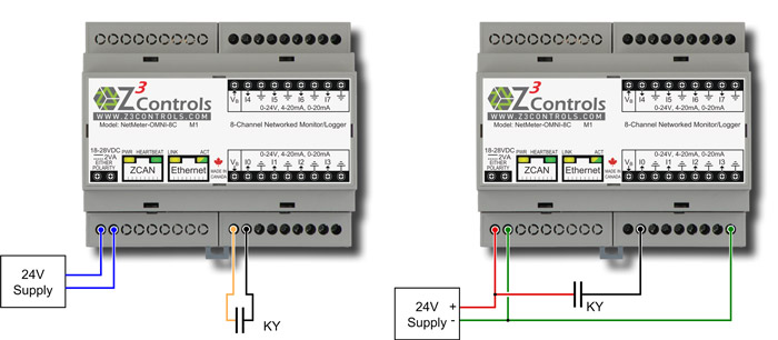 Connection Options for a KYZ Pulse Device, Backup Powered (left), Non-backup Powered (right)
The advantage of the circuit on the left is that backup power is supplied to the contact using the VB terminal. This circuit is intended to be used when the sensor/meter may produce pulses even when utility power has been lost and these pulses need to be captured.
When the contact is open, the voltage at I0 will be 0V ± some small noise voltage. When VB is applied to a single input channel, it can produce about 2.2V. VB will continue to produce a voltage even when power to the NetMeter-OMNI is temporarily lost.
Backup Power
An energy storage device inside the NetMeter-OMNI-8C allows up to 2 input channels (any 2) to continue to count pulses even when primary power is lost. This ensures that the pulse accumulation function will track the pulse output of the sensor even during blackouts.
Each VB terminal should be used to connect only a single input channel through a KY contact. KZ contacts may also be used but this will reduce the backup duration.
The duration of backup power is dependent on how many channels are in use and what percentage of the time switch contact is closed (that is why KY switches are preferred). A low duty cycle single contact should provide at least 12 hours of backup operation. Once power is restored, the internal energy storage will be trickle charged. The energy storage device does not require servicing.
Since the backup voltage is small, the threshold voltage should be carefully configured and the connecting cable should be shielded and is short as possible. Suggested threshold settings are:
- Low: 0.9
- High: 1.1
Wetting Current
In some cases, mechanical contractors require a wetting current in order to function reliably. Wetting current is the minimum electric current needing to flow through a contact to break through the surface film resistance. Below are two examples:
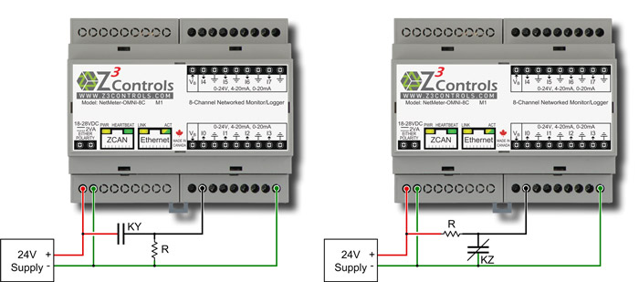 Connection Options for a KYZ Pulse Device that Provide a Wetting Current
For either of these circuits, the resistor value (R) should be chosen so that enough current flows through the switch to generate the desired wetting current. When configured for voltage mode, the input impedance of the NetMeter-OMNI will have negligible effect on the circuit so that R can be calculated as follows:
| R= | VPSU | Where VPSU is the power supply voltage and I is the wetting current. |
| I |
Here are some examples for a 24 V power supply:
| Current (mA) | R |
Closest Standard Value |
|---|---|---|
1 |
24KΩ |
22KΩ |
5 |
4.8KΩ |
4.7KΩ |
10 |
2.4KΩ |
2.2KΩ |
20 |
1.2KΩ |
1.2KΩ |
Note that either normally closed (KZ) or normally open (KY) contacts may be used in either of the above cases. The case is shown are for the default polarity of low-to-high pulse edge. The opposite switch polarity may be chosen by using the high-to-low edge setting in the “Sensor Configuration” page.